I have a Fluke ScopeMeter 97 that's come in really handy over the years. Before I got it, it was a sales rep's demo unit, so it was used pretty hard. The screen backlight is an electroluminescent panel, and their intensity can fall off pretty dramatically over their life. This particular display is also transflective, which makes it extremely readable under direct sunlight, but means the backlight is essential to using it in indoor lighting. To use it in the past, I'd shine a bright desk light on it, but I've always wished the backlight would just work.
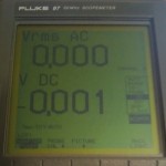
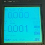
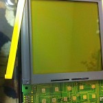
- Before replacing the panel, the screen looked virtually the same with and without the backlight turned on. It looks fairly readable in this photo, but it's really not.
- Original EL panel with spring tab contacts barely produced any illumination.
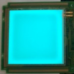
- Replacement EL panel produces copious illumination.
I finally took the meter apart and checked that the driver circuitry was putting out a reasonable voltage and frequency — it was. Clearly, the EL panel was just shot. Searching around, I found several sources for replacement panels, but I ended up going with one at SparkFun since I needed a few other things from there anyways. The cool thing about EL panels is that you can cut them to whatever size and shape you want, as long as you leave the electrodes attached. The original panel was 3.5" so this 10cm panel would be perfect. I tried to copy the active area of the old panel and trimmed the panel to size, ensuring to trim off the side that would leave the most of the edge electrodes connected, and sealed the edges with clear tape.
Of course, the original panel was connected by spring tabs near one edge, while the connector on my replacement panel was soldered and in the center. I was able to make this work by tucking the wires along the edge of the LCD and soldering them to the large pads originally for the spring tabs. I also had to cut out a few notches in the plastic to get enough clearance for the tab.
I put it all back together and … IT WORKED!!
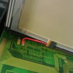
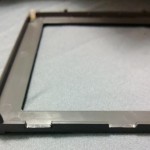
- New EL panel soldered in place. Tab sticking down in center of panel protrudes into notch in bezel.
- Notches in plastic LCD bezel required to accommodate connector and wires on new EL panel.
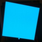
- Screen illuminated by the newly-installed EL backlight. Success!
Edit: Here are a few more photos and details about the LCD assembly. As before, only do this if you are comfortable working on things, and at your own risk.
There are two screws that hold the top cover on, and there are two more screws in the battery compartment that hold the back case on. With those removed, you can swing the back cover open. The LCD is attached to the board with 3 spring clips, which are visible from the back side with the board still installed. There are a few screws through the board that will need to be removed, then the board can be lifted out of the case. Once the board is free of the case, the three spring clips can be carefully pried off. Then, the LCD assembly will come free of the board. There are alignment pegs at each corner, so the main concern is keeping the contact pads on the board and the contact strip on the LCD assembly (gray with a black stripe through it) clean and in position. If you put things back together and end up with lines in your display, disassemble everything, make sure there are no specks of dust or oils on those, and reassemble. It may take a few tries if the alignment gets messed up, but it's possible to get it back right. On my LCD, the backlight was just held on by 4 pieces of tape. Very carefully, peel off the tape, and remove the old EL panel. Remember, you are working with the LCD itself. At this point, how you proceed depends on the panel you were able to find. In my case, I had to cut it to size, making sure to leave as much of both electrodes as possible; then I had to run wires from the tabs on the new panel over to the tabs on the board. Once that was done, assembly was just the reverse of the above.
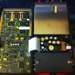
- Open scope showing location of LCD at top left, with only the clips visible at each edge.
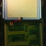
- LCD folded back showing placement of new backlight EL panel.
- Clips on each side of the LCD hold the LCD stack to the main board. Pegs align the assembly, so keeping the contacts clean while the stack is disassembled is the main concern.


I would like to hear if it was easy to remove the old panel ? From what I have read it requires extreme caution. Any pointers would be appreciated.
thanks
Robin
On mine, it was originally attached with a small strip of adhesive around each edge.
Time had degraded whatever they had used, so on mine I was able to work the old panel free pretty easily.
Obviously, it's on the back side of the LCD, so you do have to be fairly careful.
Maybe if it was really stuck, heating it with a heat gun would loosen it enough to remove it.
OK and thanks for the details. Mine is a Fluke 99 and from what i have read some other places there may be a polarization sheet between the light panel and the LCD. Did your have this?
Also, was it quite straightforward removing the entire LDC panel from the PCB? I diod have a look inside mine once but stopped to get more info before attempting anything.
I have ordered the blue-green panel …from what i can see this may be what you used?
thanks again
Robin
I wouldn't say it was difficult to remove the panel if you pay attention to how it goes back. On mine, the panel was one unit, without a separate polarizer, that the backlight attached to. I'll open mine up and take a picture of what it looks like. I used the white EL panel, but the color they come out depends a lot on the voltage and frequency of the driver. Since I didn't modify the circuitry, it came out pretty blue.
Hi, you said you sent a pic of your "how it looks like" can you please send me it and aslo any other info to buy the right panel ? Does the wiring has any polarity?
Thanks
I added the photos and a little bit of information about the disassembly process to the article itself. The particular panel is not very critical, it just needs to be close to the right size. EL panels can be cut down, but they have to be cut in a certain way to leave the proper electrodes. The EL panel does not have a polarity; it is driven by an AC signal.
Thanks for the help. I replaced mine today and it works just fine. A few things I had to be aware of was that the connecting tab on the EL panel was too large and had to be trimmed, the wires remounted at 90 degrees so they run along the bezel. When I powered up for the first time the system was dead, but it seems like it needed some initial boot to get it running, and after that everytning is just fine.
Robin
Cool! Glad to hear that it worked out for you!
Hi, My 97B Scopemeter have the EL Backlight is bad, the question is: I can use EL Backlight from old Laptop, cutting the square?. Best Regards
It is possible that it could work. You have to be careful where you cut to make sure that both of the electrodes have a connection to the panel after cutting. Depending on where the pins are, this may or may not be possible.
Thanks for sharing your Scopemeter modification, great work!
Could you please detail a bit, on how you verified the backlighting driver circuit? My newly acquired unit is missing a transistor (V1307) in the backlight circuit. Someone has clearly removed it from the PCB. I will replace this transistor and test the circuit before attempting to replace the EL panel.
The EL panels are constructed a lot like a capacitor — there is a transparent electrode on each surface, and the EL material itself is semiconductive at best. So, to get current to continually flow, we have to apply some kind of AC voltage. Also, for these larger panels, that voltage is pretty high. In fact, to just quickly test one of these panels you can (taking appropriate cautions) just plug them into household AC, at least here in the US at 110 V.
To test the driver circuit, I just used a multimeter to measure the AC voltage at the panel terminals, which I think was about 60 V. If you have the ability to measure frequency, you can also check that. I don't remember exactly what it was near, but I'd say somewhere in the neighborhood of 5 kHz. Both voltage and frequency will appear higher if there is no load from a panel on the circuit.
Hope that helps! By the way, in case you don't have it, on the schematic V1307 is listed as a BCX54 transistor.
Thanks for the information.
Per your suggestion, I checked the original EL panel by applying mains power. It lit up uniformly but did not seem very strong. Perhaps the higher frequency of the inverter inside the scopemeter will make it more luminous. If not, I will replace it with the Sparkfun unit you cite.
I'm waiting on a Digikey order for the transistor. I do have the service manual, and find it very informative. Hopefully there is nothing else wrong with the circuit. I will follow up with the inverter output specs, loaded and unloaded.
Thanks
Well, I replaced transistor V1307 and tried the back light. Alas, it was still not working! A scope on the spring contact tabs revealed a very weak, and a bit complex, AC signal. It was clear the oscillator was trying to do its job, but something was preventing the full inverter output, and messing with the Hartley circuit too. I looked at the circuit with that in mind and started checking the most suspect components. After a couple capacitor, diode, and transistor checks, I found that the electrolytic cap C1302, was barely registering, just a handful of pf's! After waiting for another Digikey order, I replaced the faulty cap today, and I am now with backlight! The EL panel looks pretty much the same illuminated with mains AC, as it does in the scope's circuit. The panel output is uniform, just not very bright. I will put the unit back together and check it out in the real world, before I replace it.
The following are measurements I took for the backlight circuit, at the contact tabs:
UNLOADED: 107.5Vpp at 11.186kHz
LOADED: 91Vpp at 982Hz
I replace the EL back light blue OK but reading still dim ,contrast changing ???
If you've replaced the panel and it's still not working correctly, then there is most likely something wrong with the other components in the driver circuitry.
FLUKE 97 Scopemeter lost the backlight
Well… it looks I have similar problem ..as yours
Perhaps you guys took some pics form the steps or can you describe te procedure? (probably too late to ask for pictures because you already assembled yours) mine is also a Fluke 97 portable scope that was dimming slowly the backlight but still the meter works.
Thanks for your help
I forgot to say that mine was loossing progressively the backlight
Thanks for the detailed instructions, I did exactly the same as you, ordered the same panel, opened the scope, used the old panel to cut it to the right size, installed, redo all the steps backward, success !
I had vertical lines missing the first time, re-opened, cleaned the contacts again with Q-tips and alcohol, done, no missing lines anymore…
Not for the faint of heart but it's worth it.
Thanks again !
Eric
thanks for the tips , this is on my maybe todo list ad my panel is dim
Replaced surface mount cap C1302 and it lit right up. I used a standard cap and bent it over a little bit to fit in the case. Try this before replacing the EL panel. Thanks!
Hey vodwarranty can you please send me a picture to know where isnthe capacitor you replaced?
Can one of you guys. Post a schematic. I have a scope 105 series II and cant find the circuit diagram to debug.
Also hate the cheap ass foil keyboard Fluke uses.
Hello
I'm French
thank you for you tutorial excellent !
I ' would like to know which voltage to choose because the Sparkfun link didn't work , so I found anaother sellers but he propose différent voltages 3/5/12Vcc => which I must choose ?
thank's
Electroluminescent panels usually work at a much higher voltage. Are you sure you have the correct product?
I also have a Fluke 97, it appears that everything is functioning as it should except for the LCD screen which has mostly faded out at the center, the displayed text along four sides of the screen is a tid bit clearer. I could cycle the screen brightness using the up/down arrow keys but its not helping to make the text readable. Is it going to be more economical to trash it and get a new on or get it repaired, is the LCD screen panel or the back light that needs to be replaced?. Any review recommend place to get the needed replacement parts?. Any inputs would be helpful and appreciated. Thank you all.
polarizer on sreen .i just change one by myself
I have a fluke Phillips 97 scopemeter which won’t power on. Can anyone recommend a repair shop or someone to fix it. I am in central Scotland. Thanks
hello, I have a scopemeter 97, the light turned on very dimly and then turned off. I changed the capacitor c1302 and now it stays on but the brightness is always very weak. I also hear a hum coming from the panel. is it necessary to replace it?
If you can measure the waveform or voltage on the panel there’s some rough numbers above. If it is in range with those now, yes it’s most likely the panel is just dim and needs replacement. If you take the panel out of circuit and can *safely* apply a 60-120V AC signal of some kind briefly, you can test the panel output.
I managed without disconnecting the panel about 56v. The hum seems to come from the panel and not from the coil. I'm afraid the lcd pen did not lose alignment of the comtacts. But I'll have to do it. Thank you
Hello all !
do you know what type LCD compatible with original lcd of fluke 97? pls help me . i need buy new lcd compatible with original lcd fluke 97 . pls help me.thanks
regard
Hung