While waiting for parts to arrive to build a proper optical serial interface, I really wanted to get some screenshots off of my oscilloscope. Knowing that the infrared LED in the interface is directly transmitting the serial signal, I figured I should be able to tap into that driving signal to obtain the serial information.
Note: since writing this article, I've built a proper optical interface.
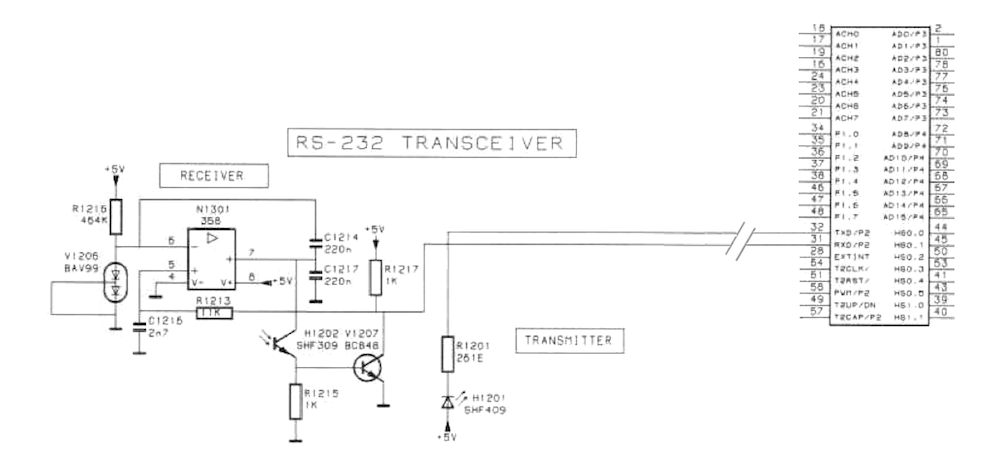
I pulled out the service manual and located the serial port circuitry. Below is an excerpt of just that section. You can see the infrared LED, H1201, is directly driven, through a 261Ω resistor, from the TXD pin on the main controller. Thus, I should be able to pull the signal from the "far side" of R1201. The location of that resistor is pointed out in the image.

Placing a probe on the resistor, I was able to verify with my multimeter that it was a 5V signal and that it did swing around when I hit the print button on the scope. Since I was still waiting on my USB-to-TTL Serial converter to arrive though, I had to find a different way to capture the signal.
Enter, Arduino.
I rigged up an extremely simple program that sets up a software serial port on one pin, reads from it, then outputs the data over the USB serial port back to the PC.
#include <SoftwareSerial.h>;

SoftwareSerial fluke(4, 13);

void setup() {
	fluke.begin(9600);
	Serial.begin(9600);
}

void loop() {
	int tmp = fluke.read();
	if (tmp > -1) {
		Serial.write((uint8_t)tmp);
	}
}
With that running on the board, I attached a probe from pin 4 to that resistor on the scope board.
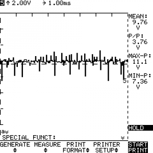
I configured the scope for ThinkJet format and 9600 bps under the "Special Funct" menu, then hit "Start Print". I used CoolTerm to capture the stream to a file, which left me with a raw stream of data meant to be interpreted by a printer as old as me…
Luckily, lots of other test equipment outputs in this format and someone has had the misfortune of already needing a translator — the Netpbm project has a program called thinkjettopbm that will convert that raw stream into a PBM image which can then be converted to PNG with pnmtopng.
Voila!
1 Response
[…] finally got around to building an optical interface so I don't have to use the hack I came up with previously to take screenshots or capture waveforms […]