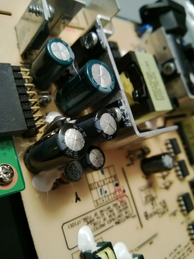
A while back I picked up an ETC M631 Arbitrary Waveform Generator for $5 at a hamfest. The seller knew it worked, but had not used it in many years as it attaches to a PC via parallel port. Figuring it was a simple matter of reverse engineering some commands sent over the bus, I paid the five bucks and added it to my project pile.
Some info still exists online about it at least. There's an old product page for it with some specs in German. I also found that the manufacturer's site has relatively complete support downloads including a user's manual, software, and drivers.
Looking through the manual and programming guides didn't provide any immediately-obvious interfacing hints. I have an old laptop that I keep around solely because it still has physical serial and parallel ports. I hooked it up to that, figuring I could put a logic analyzer inline and work out the commands that way, but I wasn't able to get it to interface. The parallel port never really seemed to work that well as a bidirectional interface even back in the day — there were always cable or driver or configuration issues — so that wasn't too surprising. It turns out that the company actually produced a USB interface for this device at one point, but it also had outdated drivers so even if I could find one cheaply (or at all) it wouldn't really be useable on modern hardware.
My next step was to take a look at the software. I pulled it up in a disassembler and saw that it mostly just passed off the commands to a driver DLL. This DLL would then translate the specific command for the generator into things like register reads and writes to be communicated over the parallel port. The main functions that actually carried out these port reads and writes would look at the instrument settings and either make a direct ioctl when running on parallel port hardware or pass the request off to another DLL when running in USB mode. This was my in to making it all work.
First, I disassembled the USB DLL and extracted the method signatures for all of the functions it exported, then recreated a shell wrapper. Initially I just added logging functions so I could determine the order various steps happened in. When I found a return value that was critical, I would stub that in as well to allow the initialization to continue. This let me identify all of the functions that would be needed to successfully bring up the hardware.
Working from there, I used an Arduino to connect to the parallel port bus lines and wrote a program that would receive serial commands to put various values onto the bus. In the new DLL, I added code to output those commands to the Arduino via serial port. Eventually after some debugging and a couple more trips through the disassembler to figure out a couple of things that I hadn't quite fully observed and I had a fully-functional Arbitrary Waveform Generator!
Now, to test it out with something more than a sine wave!
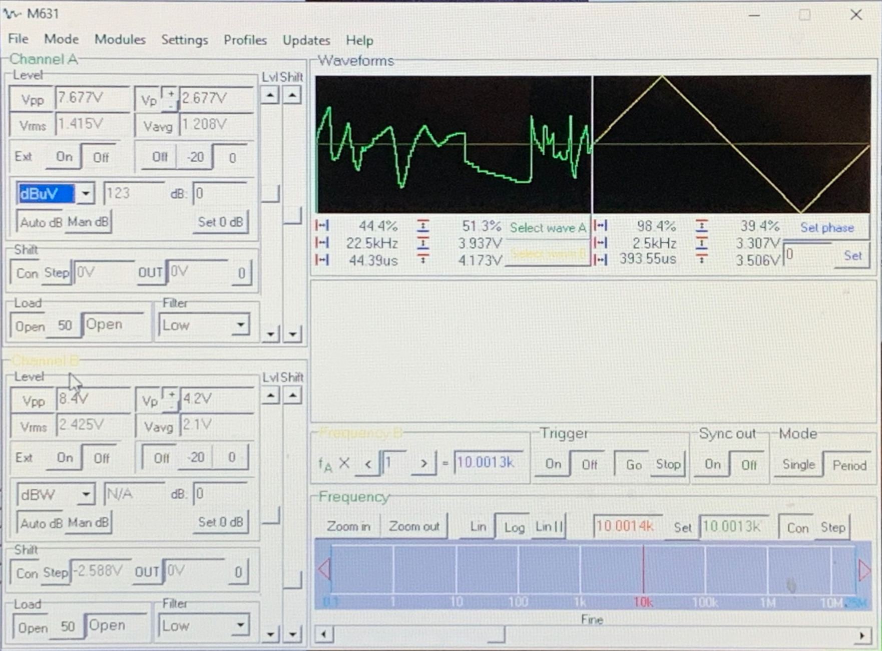
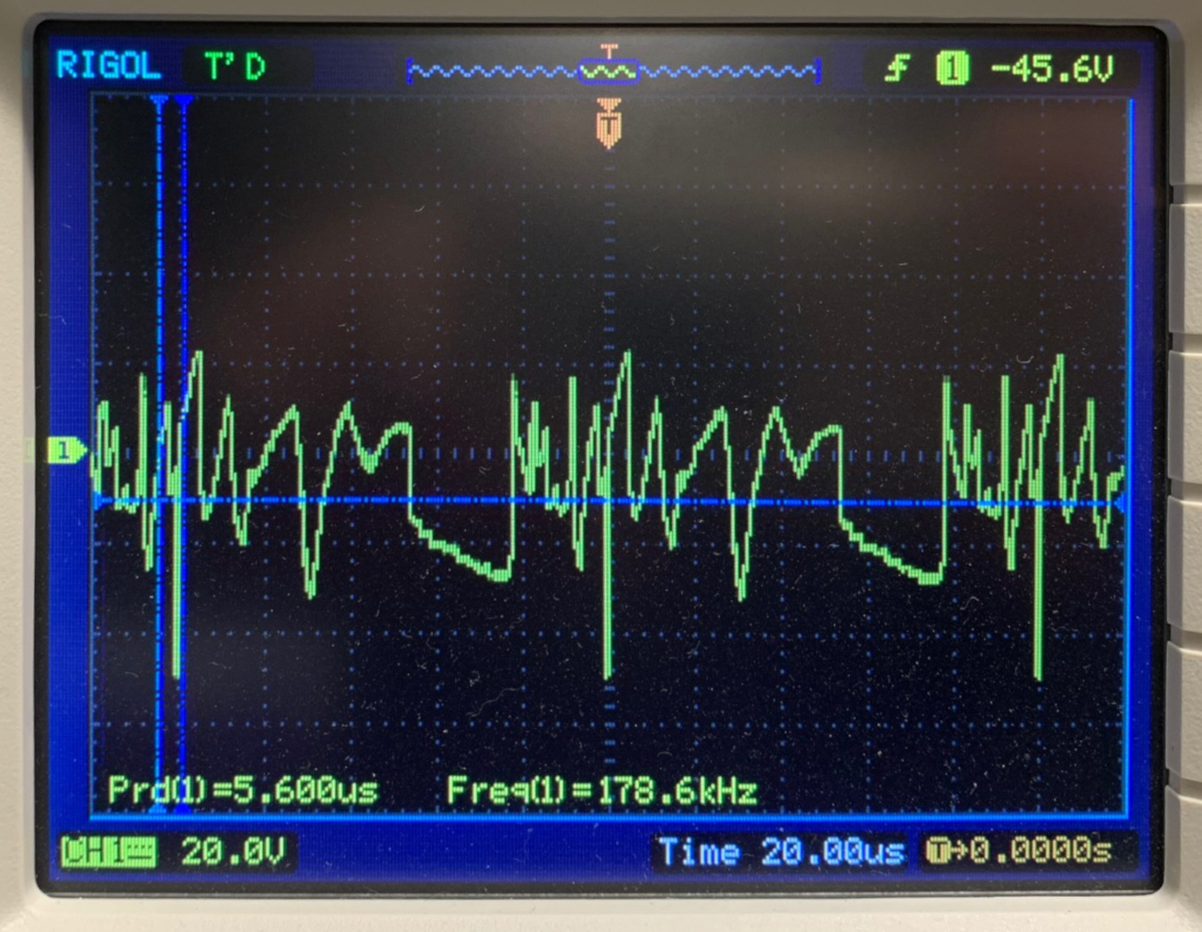
Drawing a truely arbitrary waveform in the software shows exactly that output repeated on the first channel.
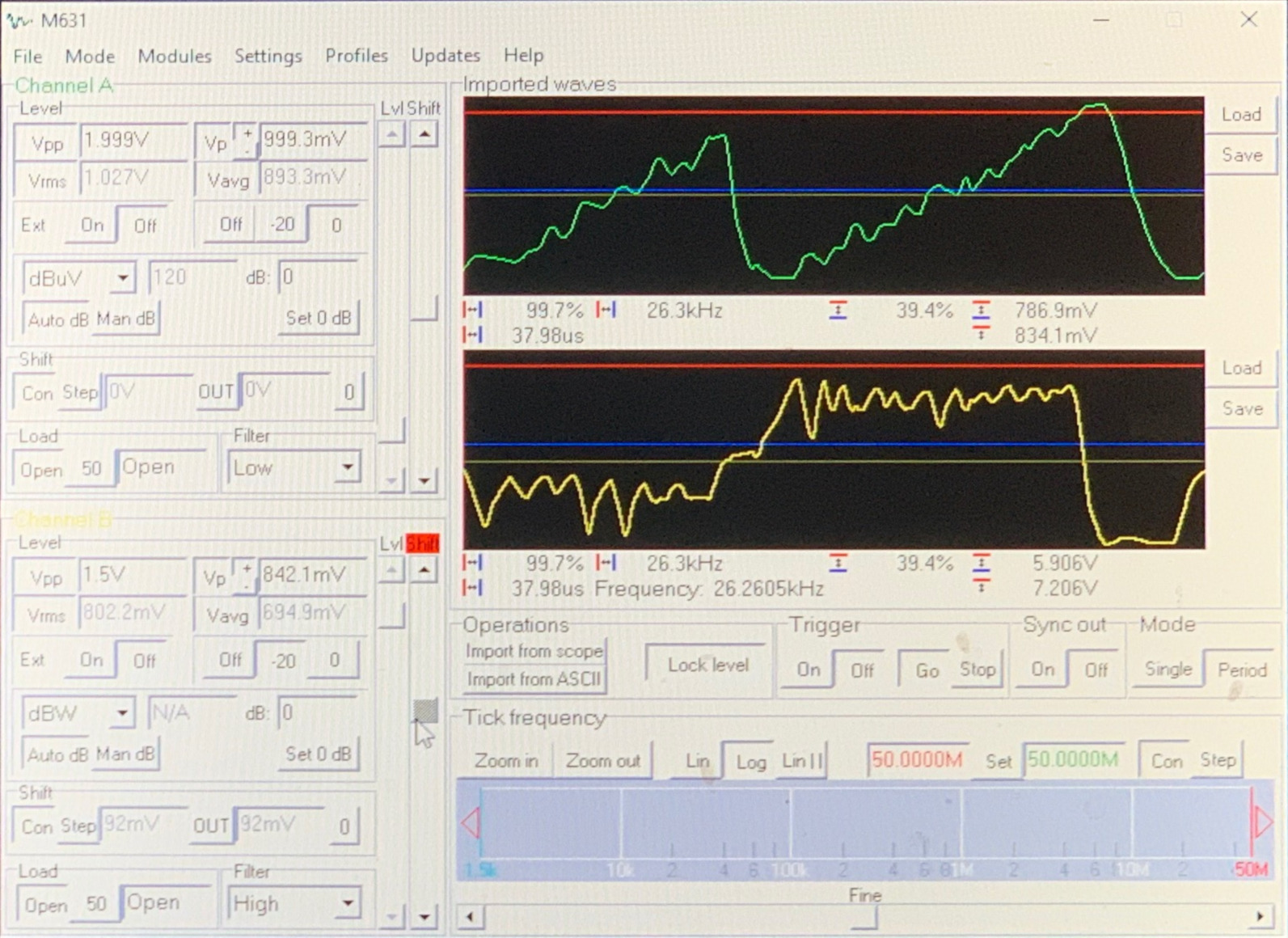
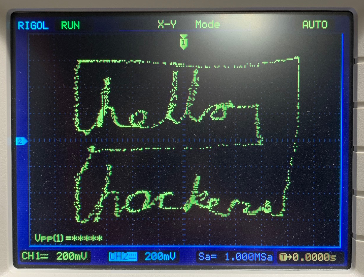
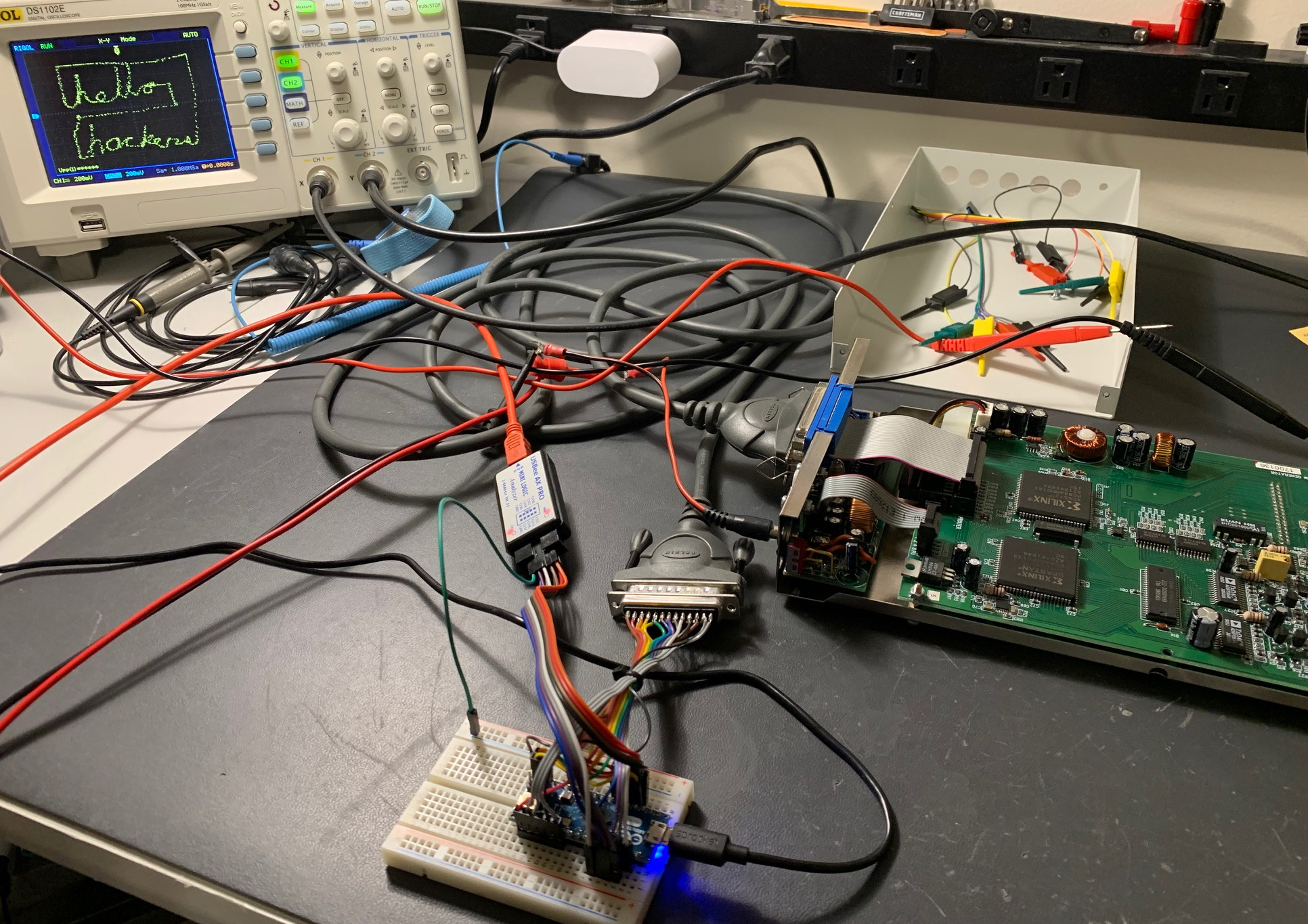
As a final test, I threw together a little program where I could draw with my mouse and it would output the XY coordinates as two waveforms I could import. Combining this with XY mode on the scope would let me do a bit of oscilloscope art.
And here's the obligatory shot of the bench with breadboarded interface, a few logic probes, and the final test.
I did a couple more minor tweaks on the code to decrease the timing until things no longer worked and got it to transfer data as fast as I could. The next step will be to build a little circuit board and box to pretty up the interface but this has already earned its spot in the stack of test equipment.
I hope this gives you a little insight into some of the tools and thought processes from reverse engineering that can be used to tackle a problem like this.
